Cutoff Bin/Wood Storage

I’m sure you’ve never noticed but I didn’t exactly have the best system for cut offs and shorts.

IMG_5474-2
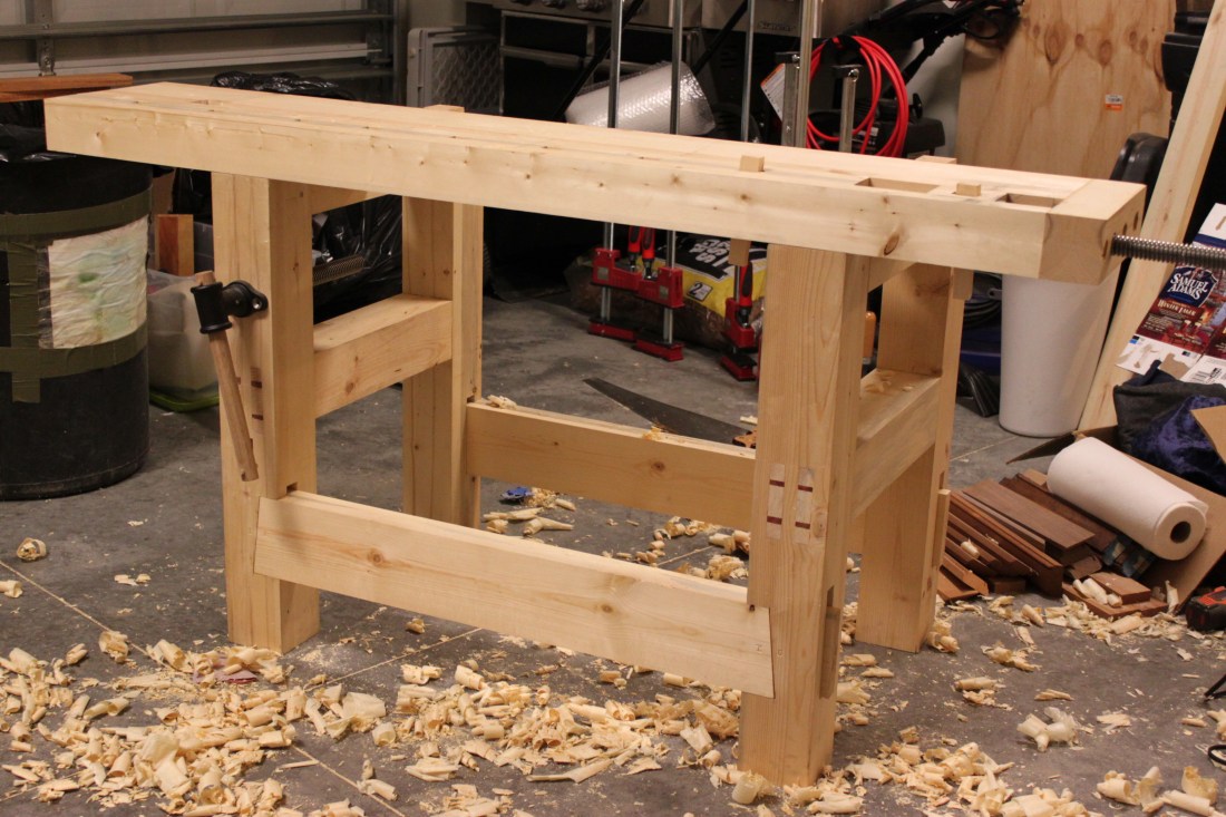
Well in all reality I don’t have a good system for any of my wood but we’ll talk about that another day. With the bench built, I’m starting to get the garage in a more productive state. That was pretty hard with a good amount of my wood in a two trash cans. It was impossible for me to know my own inventory and of course once I dumped everything out, there were pieces in there that I completely forgot I had. Out of sight, out of mind, right?

Since most of my projects are small, once I get milling, I never really have pieces longer than 48″. I looked for some ideas for cut off bins but I couldn’t find what I was looking for. I was also limited on materials. I had 8 pieces of 3/4″ plywood that measured 24″ x 35″ as well as one full sheet. I brought these with me from Pensacola and I have no idea why those were cut at those dimensions but I needed to use them up because they were just taking up space. So I began laying them out on in various ways on the floor and after about 30 min of doing so, I thought I had an idea. I came inside and put it into SketchUp and came up with this design.

Lumber Cart
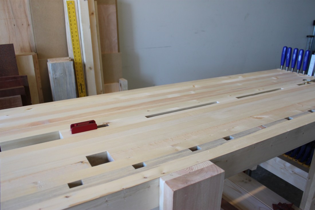
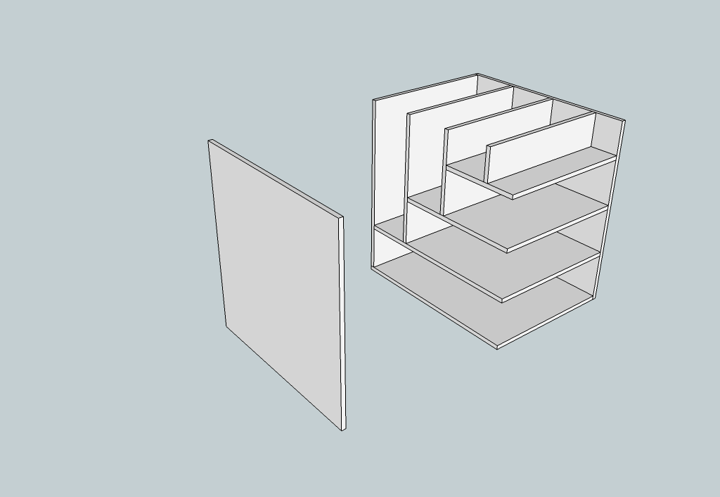
I wanted something for wide, rough cut boards I could lay down and also some vertical storage where my cut offs and misc pieces would go. The 24″ x 35″ pieces account for the guts and I used the full sheet for the sides. Each section is spaced 8″ apart and making it took about a total of 2-1/2 hours. Other than that spacing and the sides, I did not measure anything; nothing was even checked for square (and believe me, nothing is). The first thing I did was screw the back and bottom pieces so I had the basic shell and lay it on its side. Since the bottom two pieces are the same length, I measured up 8″ and made a mark. I placed the plywood on the mark and then got the vertical piece and placed it flush with the back.

IMG_5830

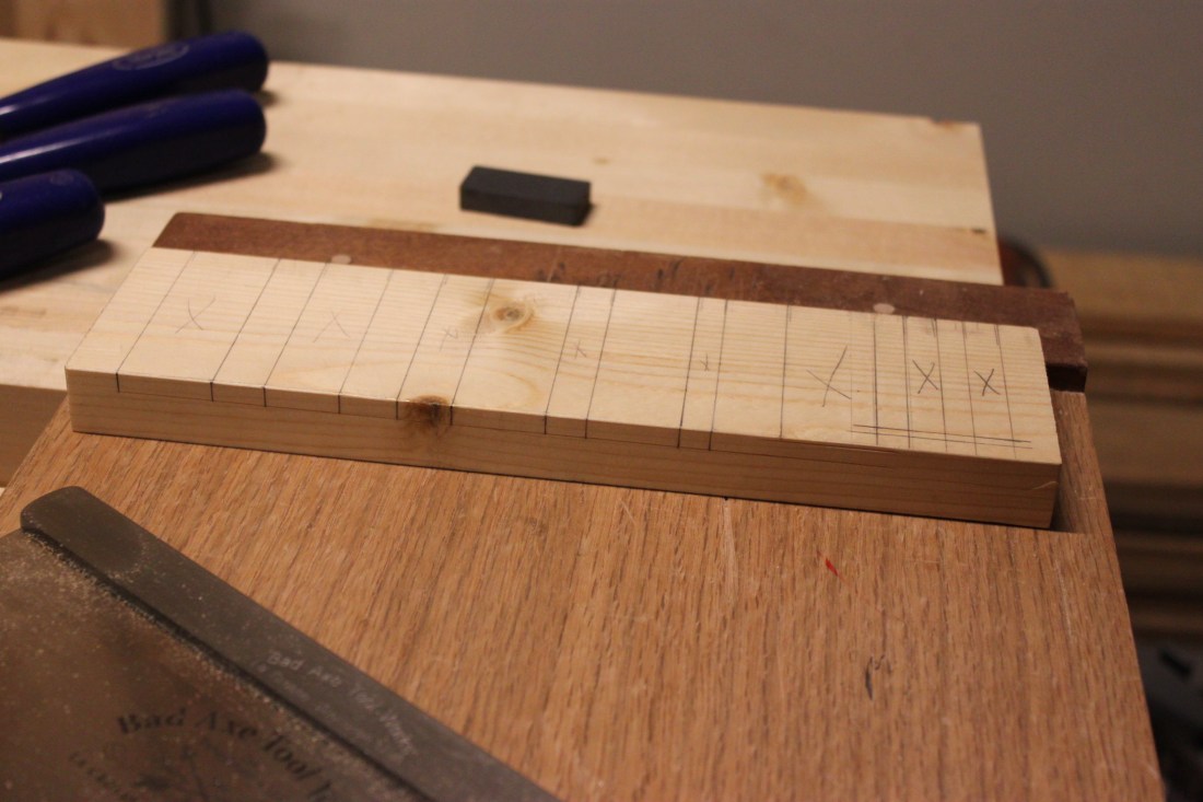
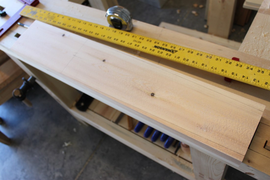
I used that for my relative dimensioning, marked and cut my piece. That piece would then in turn be used for my next relative dimensioning. I marked 8″ from the back piece, put the board I just cut on that mark and then placed another along the bottom piece and marked it. That process was done until I had all my pieces.

IMG_5831

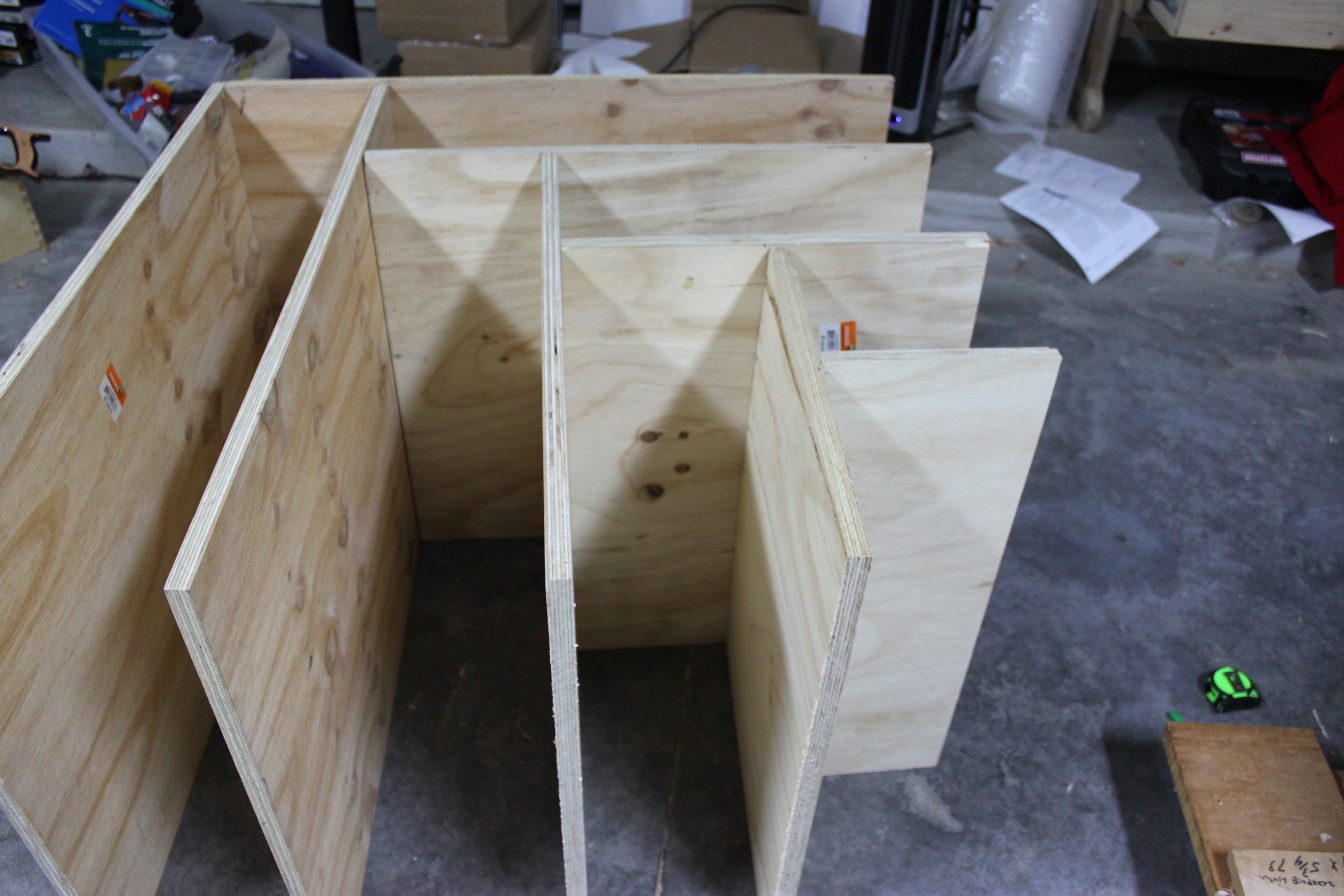
What made everything a huge PITA is that nothing was screwed so my boards were constantly tipping over as I’m trying to get things marked and spaced. It would have been impossible to screw things as I went since my spacing was only 8″ and my drill was at least 10″. So once I had all my pieces, I marked 8″ on the opposite side of the board to get things a little even and started my screwing from smallest to largest pieces. With all my pieces as 35″ long, I knew the sides had to be 35″ x 35-3/4″ without actually measuring the overall size. Once it was time to get screwin, I realized I didn’t have enough wood screws… But then I remembered I kept a box of 100 pocket screws from a kreg jig I bought a while back. I only used it once and didn’t foresee myself using it again anytime soon so they volunteered to finish the job.

IMG_5833
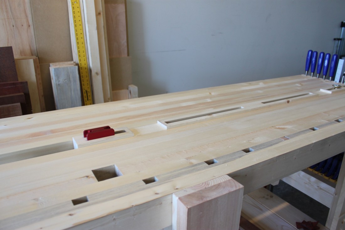
It may be ugly, but it gets the job done!!

IMG_5839IMG_5837
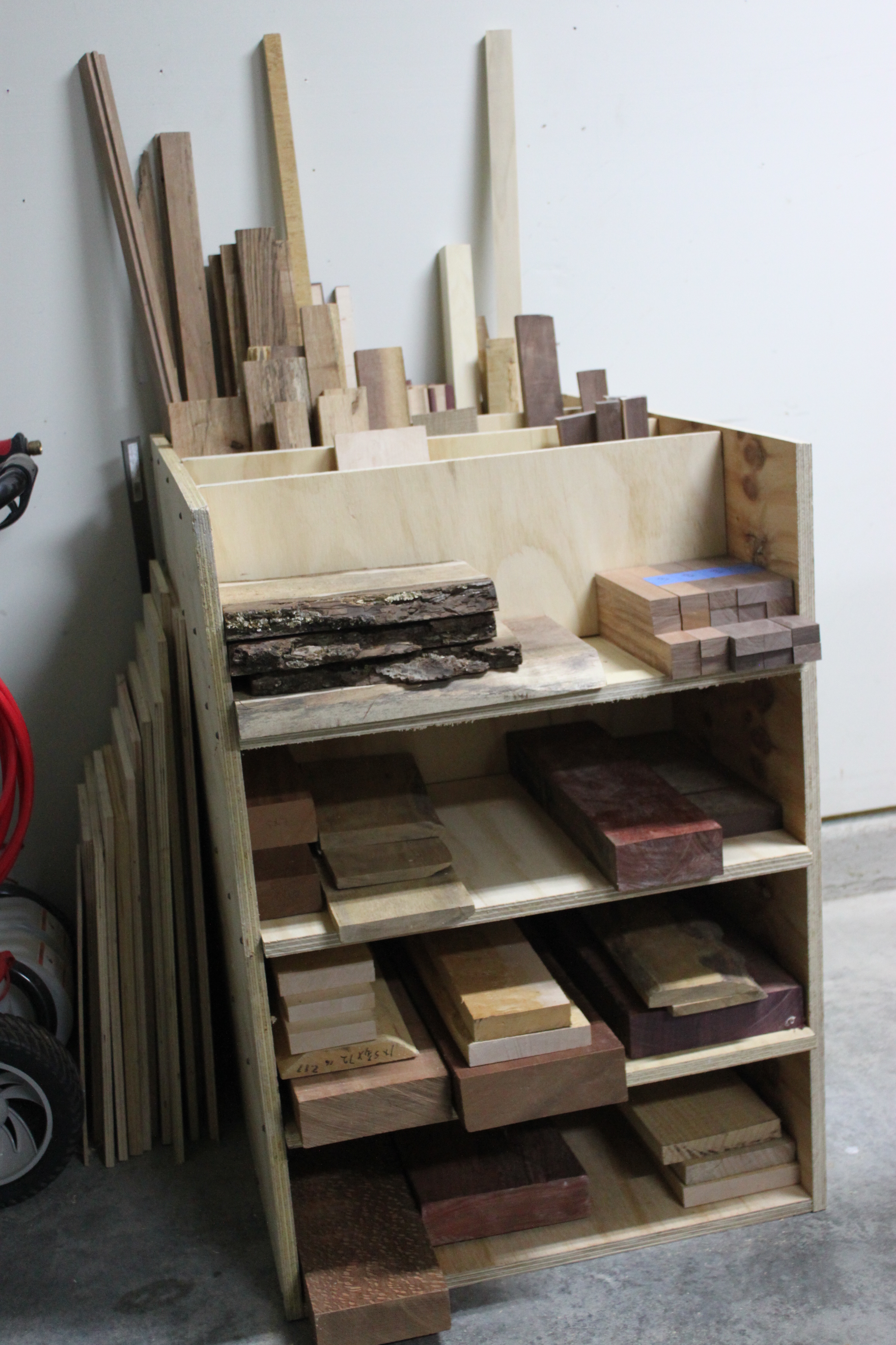
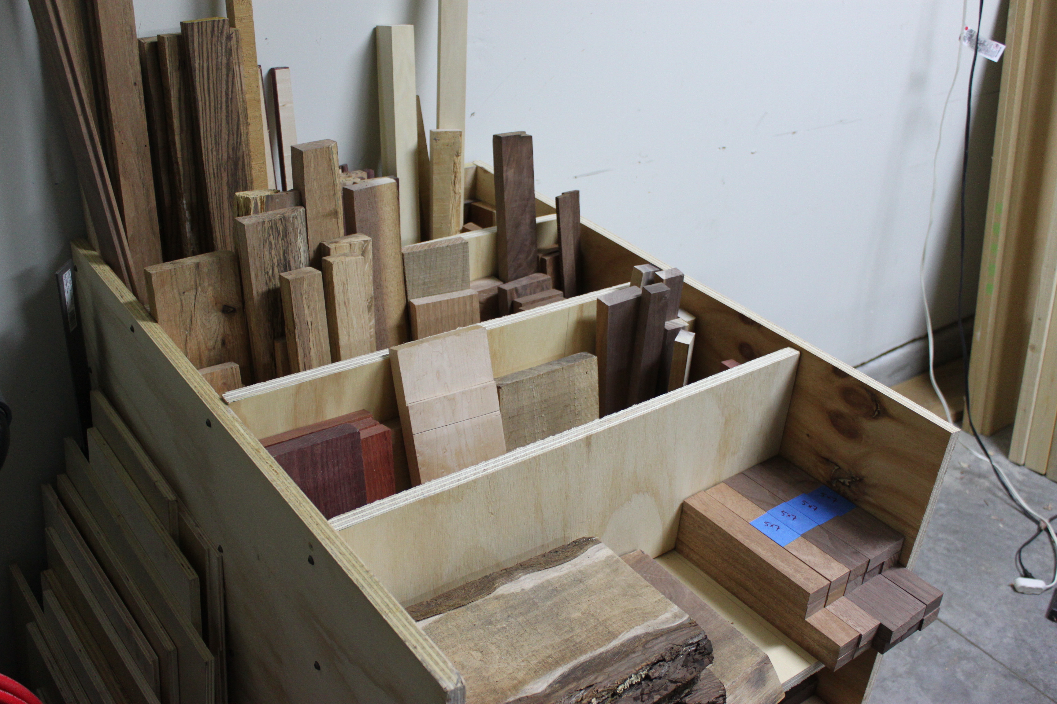
This project was much needed. My cut offs finally have a home! Next is getting my full sized boards off the floor…

FINISHED! The Split Top Hybrid Roubo

As the year comes to an end, so does my biggest woodworking accomplishment to date. It’s been seven months in the making (well five if you don’t include the two months I was gone) but I can finally say that my bench is done!  Split Top Hybrid Roubo At this point in time, I’ve decided not to use a finish on the bench. I’ve read many discussions and articles on the topic and to my own conclusion I’m leaving her al naturale. As you can see, I did decided to add the chisel holder on the side where I mis-measured.

IMG_5733It almost seems like it was all intended. Making it was quite easy. There was the set up.

IMG_5719

The layout.

IMG_5720And then cutting the dados.

IMG_5726Yes, the magnet is a bit of an overkill for just a ruler but since I had it on hand I figured I might as well use it. I attached it with two wood screws and basically fixed my mistake.

The center piece worked out better than I hoped.

IMG_5725The space between the two tops was 2-3/8″ so just shy of using three laminated pieces of 3/4″ stock. I used S4S pine from the big box store to knock this out. Only the center pieces were milled to get a snug fit. In order to get the flush fit on top I needed to notch out the space where frame was.

IMG_5721Again some simple dados.

IMG_5724

Once these two projects were knocked out it was time to attach the top to the base. For this I took off the top and measured 6″ from the sides and centered on the base and drilled through with 3/8″ auger bit. I put back on the top, marked where the hole was on the bottom of the top, removed the top, drilled that hole in the top, and reattached the top. I would have liked to sink the lag screws into the frame but I didn’t plan ahead so there was not enough clearance to drill from the bottom. They are attached with 1/2″ x 3-1/2″ lag screws but I’m gonna extend those to 4-1/2″ at a later time.

With everything done, it was time to flatten it all. Overall it wasn’t too bad but my left side was sitting a little low. IMG_5713About 20 min worth of planing produced a flat top.

IMG_5736And here’s a shot with the center piece flipped.

IMG_5737It extends 3/8″ above the surface and works great. I actually used it to finish up the chisel holder.

IMG_5730IN SUMMARY:

This bench was built entirely with hand tools. Not a single  power tool was used. Plans were modified by me from Fine Woodworking’s Hybrid Roubo Bench. Other than a couple of S4S pieces of pine, all the wood used is construction grade 2×6 from a big box store. Vise hardware for the wagon and leg vises are from Lie-Nielsen. I wish I would have documented actual build time but it took five months of weekend and after kids go to bed shop time. Thanks for looking.

Benchtop with a Bench

I’ve already established that my bench isn’t finished but it is usable. That’s enabled me to complete a few projects to get a little bit of woodworking income which in turn has steered me away from making any progress. Well I’ve finally made it back to bench building. Thinking back to the very beginning when I first started building the front half of the top, I thought of how my knees would ache from all the hours of milling on the ground just to get the first eight boards laminated.  Those painful memories have begun to fade.

Using the bench to mill the boards for the second half has not only made the chore less painful on my body but has also allowed me to complete it in a fraction of the time. No more planing on the floor, checking flatness with the winding sticks on the saw bench, back to the floor, back to the saw bench, etc… With the use of the bench, I seem to have been able to knock out the complete second half in just two days of after work shop time.

Since there was nothing exciting about building the other half of the top, I didn’t document anything. I did take the time to take a shot after I cleaned it up after I got it out of the clamps.

IMG_5710I did get the mortises in the top but let me just say it was about 2230 (1030 pm for you non military types) when I did them… That being said, I may not have measured things with my full attention. I cut my mortises at 10-3/4″ from the right side instead of 11-3/4″ so things are a little off.

IMG_5711I have no intentions on fixing it either. I thought about adding a chisel holder there but we’ll see. Although she looks done, there is still quite a bit left to do. The left side still needs to be trimmed flush with the front, gotta make the planing stop, I have to build the center piece, secure the top to the legs, flatten the top and finally add an oil/varnish finish. I may actually meet my end of 2012 deadline!

Leg Vise and the Ugliest Slinding Deadman

Have you ever got to a point in a project where you’re so close to being done that you just can’t get yourself to finish? I seem to be at that point with my bench. I have however been able to knock out the rest of the leg vise and the sliding dead man. The installation of the leg vise hardware was pretty similar to the wagon vise with few exceptions. The threaded rod for the leg vise was 1/8″ thicker than the one for the wagon vise for a total of 1-1/8″. My largest auger bit is a number 16 so it isn’t large enough with the bit alone. Once I got the hole drilled all the way through I took the rod and threaded it through and since the pine is so soft it was able imprint the sides of the hole.

IMG_5489I used a 1/4″ chisel to pare away the walls until all the threaded marks were gone. Once the rod was able to slide through without force I assembled the hardware so I could mark out the fitting.

IMG_5490I know I took more pictures of the assembly but I cannot for the life of me find them. Anyhow, it was pretty much the same as when I did the wagon vise install and in my last post you saw that the hardware was already complete. So what I’ve actually been able to accomplish from that point was the actual leg portion of the vise. In my original design, I was gonna go for something like the design for the “18th Century Workbench” that Chris Schwarz made. I decided against that for a couple reason and the main one being available tools. I didn’t want to buy any rasps or coping saw for the curve work. Instead I went for a simple taper. IMG_5510

Just like the stretchers, I used a 2×6 and some big box store 1×6 to get roughly 2″. I didn’t measure the thickness but left things as thick as possible. I know you can’t tell but there is a nice birdseye figure to face of the vise. Once everything was flat, square and parallel, I did a dry fit.IMG_5511

As you can see, things weren’t quite flush. I took everything apart and examined the bench surfaces. IMG_5512

Part of the leg wasn’t quite flush with the bench top as you see above but it was actually more towards the stretcher where there was some unevenness. After a bit of planing I had a better fit but still needed some work.  IMG_5513

Next was working on the parallel guide. Since I had already cut the through mortise when I assembled the legs it was just a matter of transferring location on to the vise. I couldn’t take the measurements and mark it out on the leg vise because I had already cut the tapers, so I clamped the leg vise to the leg of the bench and did my best to trace out the mortise for the parallel guide. After I couldn’t get a good trace with a pencil I took a chisel and lined it up with the walls of the mortise as best as possible and marked it out. IMG_5514

After the mortise was cut I made the parallel guide to fit snug in the leg vise but a hair smaller than the mortise of the bench leg so things would slide smoothly. Once I was happy with the fit I bored out the 3/8″ holes which were offset by 1/2″.

IMG_5515

If you think that the parallel guide is ugly, just wait… Now that I  had all the componets complete it was time for a dry run without the screws on the vise. Everything seemed to move smoothly so I figured I was ready to tighten things down. For some reason I decided to do this with the vise half way pulled out. When I went to check the fit I actually got it stuck. I could close it all the way but getting it to back out I had to reach under and lift the parallel guide for it to come loose. At first this worried me and I couldn’t think of what I was doing wrong. I’m gonna blame it on the fact that it was probably around 10pm and maybe after a beer or two. After some tweaking around a bit I figured it out. I closed the vise, clamped it down and then tightened the hardware. This gave me a smooth operation all the way in and all the way out. IMG_5541

I don’t have any fancy draw bores or wooden pegs so I just use what I have and in this case it’s a allen wrench. IMG_5542

Now I didn’t really document the sliding dead man but I did want to show how ugly it was. Auger bits and pine do not seem to like each other. No matter what I did, drilling fast or slow, little pressure or a lot of pressure, things were just UGLY. I honestly think it’s the “craft” wood from the big box stores because I didn’t get these results with I drilled out the mortises on the 2 by material. IMG_5543

Blow out on the back was horrible, even with a sacrificial board and predrilling the back. It is only the back so I’m not worried but I hate how compressed all the fibers are in each hole. These are 1″ holes offset by an inch so I just used the same oak dowel that I made the handles with. Overall it slides real smooth considering the track and groove are a less than perfect fit. I’m real happy with the functionality of both devices but if I could just finish up the top soon I’d be really happy. My goal is by the year’s end.

Assembling the Base

Out of all the joinery for the bench, I think this wedged through dovetail mortise and tenon was the most nerve racking. Considering I haven’t been doing the hand tool thing for too long, successfully assembling this joint would a big accomplishment for me. Although it may not seem like it, the layout was a bit tricky to read off the plans and to make it more complicated I had to modify them to fit my dimensions. Looking at it now it doesn’t see like it should have been but I guess it was the intimidation factor for me.

Here’s the inside..

And the outside layout.

The “x” marked areas serve as straight through mortise. Now I’m not sure how most do their through mortises by hand but I found it easier to drill my holes out about 1/2ish the way through

And then (mostly) clean it all up

Before flipping it over and drilling out the rest.

Once the through mortise is all complete…

It’s time to work on the angled portion of the mortise. To do this I first established a kerf that is angled down to the marked line up to the edge on the opposite side.

And slowly work back until the kerf line is gone.

Next was tackling the inset portion. To make things a little easier I made a series of kerfs with my little pull saw. It’s a lot easier to pull away from the wall while sawing then push against it. From there is was a matter of carefully chipping out the waste until I was about 1/8″ away from my line.

After I get the last bit out of the corner I take it all down to my scribe line and clean things up as best as possible.

Yes, I know she’s not a looker but she gets the job done. Also considering I’m using such a soft construction grade pine, I do have to say that it did turn out well, IMO.

Next of course comes the tenon portion. For this I must admit I somewhat cheated. The total thickness for the stretchers are 2″. As you know, 2 x 6 dimensioned lumber is 1-1/2 x 5-1/2 and when I mill things up I usually get about 1-1/4″ to 1-3/8″ depending on the board. I didn’t want to put two of these pieces together and end up with 2-1/2″ to 2-3/4″ to have to thickness down to 2″. So I just bought some S4S boards from the big box store when I went back to get a couple more 2 x 6’s.

Layout for the mortise was much simpler. I’d love to show you but I was on a roll in the shop. Once I dry fit the first one and saw how great it fit I didn’t stop for pictures. Cutting out the tenons was  a much simpler task. It was just three cuts. The first cut was for the 1″ shoulder, then I went down the board and cut the cheek. Lastly was the angled haunched portion. Here is the end result.

After I cleaned things up and fit each joint individually, I assembled the whole base.

As you can see I  also fit the top at this point. I must say, I do love it. Although I knew the dimensions when I began building, it is a little smaller than I thought. By no means is that an issue, I still think it’s the perfect size for me and my projects. I just have to remember that the zoom function in SketchUp doesn’t mean larger in real life.

I’ve also already added the leg vise hardware and will write a post about that when that portion is all complete. I even made a couple of bench dogs and although she’s not complete, she is 100% useable. All that’s left with the base is adding the shelf, making the wedges and do a final clean up of all the joints and edges before setting her in place.

Finishing the Wagon Vise

Well I was finally able to get back in the shop since arriving back home last Sunday. It wasn’t easy though. I kinda left the garage in a disarray when I left and it was no better when I got back. Yeah, that’s supposed to be my shop area… Well after three days of on and off again cleaning, I finally got my side of the garage in a usable state.

So now my first state of business was finishing the wagon vise! Before I can start on today events, let me catch up on what was done before I left to Yuma. After I finished my tenon part of my end cap it was time to cut out the mortises.

I don’t mean to brag but these mortises pretty much fit like a glove from the get go.

Next was getting the hole cut out for the screw portion of the wagon vise. Since the threaded rod has a 1″ diameter I established the center with a number 16 auger bit between the spacer and made my mark.

Once I had the center outlined I placed the threaded insert over the outline and traced it.

After it was traced I finished drilling the hole through the end cap…

And then I chopped down to the depth of the hardware and marked my holes and drilled for the mounting screws.

I did have to add a little bit of a chamfer to the edges to make room for the welding on the hardware. Once I mounted the hardware and went to dry fit it, I found out there was one little problem. Again, since the hardware was an after thought, things didn’t quite line up.

So I marked the edges of the hardware on the bench top the and cut back to the depth of the mounting bracket. Once everything was nice and flush, I left to WTI.

Now we come to today. There was one issue that was making this whole set up a real PITA. When you tightened the screw that secures the mounting piece on the moveable portion of the vise, it makes contact with the bracket before bottoming out which causes it to tighten the bracket rather then letting it spin freely. Therefore when you loosen the vise it would unscrew completely. To correct this issue I cut the top off a small screw and placed it in the screw hole to act as a spacer to give clearance between the bracket and screw.

Now I know in my last post about the vise I mentioned how I did not want to use any metal fasteners on this bench. Well while in Yuma I came to the conclusion that since I’m dealing with pine, to best reinforce the end cap it might be best to go ahead and use them. Luckily for me I already had some lag bolts and washers from a previous project that I never used. I marked for three bolt and drilled about 3/4″ down. From the center of the auger bit it continued with a 5/16″ drill bit for the 3/8″ bolts. I elongated the two back bolt about 1/16″ and 1/8″ respectively. Nothing fancy, just some paring away with a chisel.

Once it was all said and done and the end cap was mounted, I installed the vise hardware completely and cleaned up the top and edges. I used a 1″ dowel pegged with a 5/16″ dowel on both ends for the handle. Here she is closed…

And open…

In summary I would have done a lot different. First would obviously be to account for the size of the hardware before building. There won’t be too much flattening of this bad boy since parts of the hardware are almost already flush with the top. I would have also like to use up more of the vise length. There’s about four more inches of unused rod that could have been nice to have. Also, I don’t like how close the left bolt is to the edge but so long as it holds, I guess I’ll try to not let it bug me. Aesthetically, I may go back in a square up the elongated holes. You may or may not be able to tell but they are quite funky in shape.

Other that waxing the sides and runner grooves, I’m calling the wagon vise complete! I don’t have any bench dogs made yet but I did test it out by placing a piece scrap in the middle and clamping it down and boy does she hold. I couldn’t even budge the board! Next is getting the base assembled…

The Shadow Chest Concept

Since I left home for WTI back on September 5th, I really haven’t done much. I don’t just mean woodworking wise, I’m talking about day to day life. I have however manage to watch an impressive amount of TV shows. I’ve been able to start and finish or catch up to The Walking Dead, Game of Thrones, Blue Mountain State, and White Collar to name a few. I’ve also been able to watch a ridiculous amount of movies. BUT, that’s not all I’ve done (just mostly).

Since I can’t do woodworking, I’ve been Sketch(ing)Up some ideas. Now I think lots if not most hobby woodworker have some type of “business”. Now I don’t mean an official business that we need involve Uncle Sam in, but something’s gotta pay for all the wood and tools. Mine happens to be frames and shadow boxes. I mean what kind of Marine woodworker would I be if I didn’t make shadow boxes! It helps keep me in supply of wood and can sometime generate enough for new tools now and then.

Well since my wife left the Marine Corps after 8 years to take on the job of homemaker, I’ve been wanting to make her something special for her to remember her time (even if she doesn’t want to) in the Marine Corps. She did receive a shadow box from her shop upon EASing but it’s a cheap store bought one. I did offer to make hers but her Gunny did want me to make it since it was a shop gift and I wasn’t in their shop. Anyways, she’s always told me she wanted a chest to put her uniforms in so I wanted to design something that would house a (new) shadow box and her uniforms as well as any other misc items she may want in there. I know this is no new design but I haven’t been able to find anything that closely resembles the potential quality that mine has.

I may be giving my SketchUp skills more credit that what my woodworking skills will be able to produce but we can all dream right? Now here’s a few things that are specific to this chest. There are four different types of dovetails on it; a through dovetail (case), a half blind dovetail (trays), a sliding dovetail (lid), and a miter dovetail (shadow box). The hardest part of designing this chest was making it sell-able. Let me explain. If I sold this case, the question that kept stumping me was “how do I enable someone to access the mounting board of the shadow box and reassemble it after they are done?”

The shadow box is built into the lid so it’s not a matter of removing it entirely and accessing it from the back like my typical shadow boxes. Idea after idea my bubbles kept popping. It wasn’t until I re-stumbled across an article in issue#213 of Fine Woodworking that it hit me! Mitered frame dovetails!! Here’s what I’m thinking; set the sides of the case in the lid and then basically make a false front. Three of the sides would be permanently mounted with  a fourth that would be removable to access the mounting board. You can get what you need done and when you’re finish, place the piece back on and it would still look complete. While it sounds simple enough, it probably won’t be. That’s why it’s a concept.

A couple other notes that I want to mention… The lid design is taken straight from Tony Konovaloff’s tool chest. Although it seems to be completely out of my league, that won’t stop me from trying. Next, I wanted it to resemble a foot locker in shape. For that reason there is no kick plate to hide a through groove for the base so there will be a stopped groove….. I think that’s it for now. I look forward to starting this once my bench is complete!

Well That Didn’t Work How I Intended…

When I first thought about building my bench, I didn’t intend on buying any vise hardware. My original plan was to just use a bar clamp on the leg vise and a spreader for the wagon vise. Well if I’m putting so much time and effort to build this bench by hand then why not spend the extra money for presentable hardware?

A couple of weeks ago I went ahead and ordered both the large single screw vise and scandinavian vise screw from Lie-Nielsen. Now if I were building the bench larger and of higher quality materials then of course consider I would consider something like Benchcrafted but since it’s just some construction grade pine, the Lie-Nielsen will do just fine. There was only one major issue…

Since the vise hardware was an after thought, things didn’t quite fit with my current wagon vise set up. The installation would have been impossible without another modification. The other piece of mounting hardware was also an issue but more of being able to drill out the holes for the screws.

There was no room to get anything in there so I was left with one option…

After I cut out the spacer I brought the wagon vise forward and clamped it so I could drill out the holes for the screw holes.

Actually mounting this piece concerned me also due to the fact that since it was going into the block with the dog hole already cut. No matter how I angled it, the left side looked like it was going to pass through. I opted for the top left since it would give me a little more room because the top is angled more forward. The screw just barley broke through but not enough to matter.

Next was getting everything square and ready for the tenons.

I know how I wanted the mortise and tenons to fit but not exactly how to reinforce (I’ll get to that in a minute) so I began the layout. First I knocked out the single tenon with a combination of my sash saw and a flush cut saw. I needed a smaller saw that could get in between the top. After that was done, I started on the shoulders of the larger tenon. When I started to cut the cheeks I had to stop because I kept going at an angle. I didn’t want to stand the bench on end and cut so I tried sideways and that didn’t work. So I began chopping it all away.

I went all the way down to about 1/16″-1/8″

and then crept up on my line with a block rabbet plane.

I flipped it over and when all was said and done, here she is.

Now here are my issues with reinforcement. First, I don’t want to use any metal fasteners. I’ve seen many benches with lag bolts on the end cap and I just don’t want to do that. Unless absolutely necessary, lag bolts are a last resort.

Next, my tenons are 1″ long. Does that offer enough space to insert 3/8″ dowels? If they were centered on the tenon, there would be 5/16″ on each side of the dowel. That just doesn’t seem like enough of the tenon for proper reinforcement. I’m not planning to clamp boards with enough force to bow them so maybe it would be enough?

Lastly is the design aspect. I went with a shorter shoulder on the side more near the wagon vise because I wanted to get a dowel in as close to the wagon vise as possible for better strength. Probably doesn’t matter but I went with it anyway. Here’s what I’m thinking…

As for dealing with expansion, I plan to glue the mortise and dowels on the left side of the vise for a solid foundation. Now I’m think that gluing just the dowel on the right would be okay and then opening up the dowel holes laterally for the last two would allow for any movement.

The total width of the end cap is about 11″ and I know there are formulas to figure expansion and contraction but I think it’ll be fine. Anyone disagree?

On a personal note. On Wed I’ll be leaving to AZ for 9 weeks for some training. My goal is to at least have the end cap and wagon vise installed as well as the left side of the bench fully assembled. Wish me luck!

Slowly but Surely

Although I haven’t made much progress in one specific area on the bench, the base is coming together little by little. Here’s what I’ve got since my last post. All the legs and side stretches have been milled and cut to their final length.

After laying out out the joinery, I cut the tenons on the top stretchers first.

After I cut the tenons on both ends, I drilled out the mortises with a brace and then dry fit the pieces together.

At this point you can also see I cut the tenons on the top of the legs. Next was tackling the wedged tenons. My 16″ Bad Axe Tool Works tenon saw did the job just fine!

There was a lot of necessary clean up on both the tenons and mortise but believe it or not, everything fit snug on the first fitting.

I did finish up both ends and did another dry fit with both stretches but did not take a picture before I pulled everything apart. I was extremely happy with the results. Tonight I moved on cutting the mortise for the haunched dovetailed tenon. Now by no means is this pretty, but the inside will be hidden when it’s all said and done so oh well.

The left side of the bench is almost done. I have one more dovetail tenon and the leg vise installation to wrap things up. I plan on actually posting the steps/techniques as I build the right side so stay tuned for that!

Finishing the Front Half of the Top

If you read the last post you pretty much saw the completed top clamped. Here I’ll cover the dog holes and the top after it’s been cleaned up a little bit.

Making the dog holes was time consuming but not as bad as I had initially thought. I started out by first getting the angle of the hole with a bevel gauge.

I used all the dimensions from the plan to layout each hole.

Each piece had a dado cut out first. Once done, I tried my best to cut as deep into the face of the dog hole so I could remove as much as possible, as cleanly as possible. The rest was a matter of chipping out the remainder until all was flush with the bottom.

Now it was time to repeat those steps 8 more times. Skip ahead a bit and were back to everything being clamped up. Here it is fresh out of the clamps.

First task was getting the overhang cut flush with the rest of the bench. Then I wanted to find out how much things had shifted during the glue up. I pulled out my winding sticks and things didn’t look too bad.

I planed the top 45° both ways, transverse and then finally along the length. The end result was looking mighty fine.

Here’s a close up of the wagon vise. While it would’ve looked even better if I hadn’t messed up, I’m real happy how it turned out.

It hasn’t been flattened 100% nor has it been cut to it’s final dimensions and it won’t be until the other half is done. Probably not until it’s actually mounted on top as well. The only thing is that I don’t plan on finishing the top until the end. Time to start working on the base.