Have you ever got to a point in a project where you’re so close to being done that you just can’t get yourself to finish? I seem to be at that point with my bench. I have however been able to knock out the rest of the leg vise and the sliding dead man. The installation of the leg vise hardware was pretty similar to the wagon vise with few exceptions. The threaded rod for the leg vise was 1/8″ thicker than the one for the wagon vise for a total of 1-1/8″. My largest auger bit is a number 16 so it isn’t large enough with the bit alone. Once I got the hole drilled all the way through I took the rod and threaded it through and since the pine is so soft it was able imprint the sides of the hole.
 I used a 1/4″ chisel to pare away the walls until all the threaded marks were gone. Once the rod was able to slide through without force I assembled the hardware so I could mark out the fitting.
 I know I took more pictures of the assembly but I cannot for the life of me find them. Anyhow, it was pretty much the same as when I did the wagon vise install and in my last post you saw that the hardware was already complete. So what I’ve actually been able to accomplish from that point was the actual leg portion of the vise. In my original design, I was gonna go for something like the design for the “18th Century Workbench” that Chris Schwarz made. I decided against that for a couple reason and the main one being available tools. I didn’t want to buy any rasps or coping saw for the curve work. Instead I went for a simple taper.
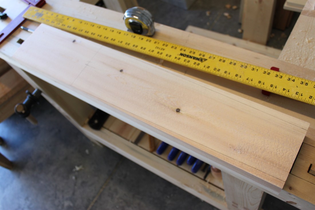
Just like the stretchers, I used a 2×6 and some big box store 1×6 to get roughly 2″. I didn’t measure the thickness but left things as thick as possible. I know you can’t tell but there is a nice birdseye figure to face of the vise. Once everything was flat, square and parallel, I did a dry fit.
As you can see, things weren’t quite flush. I took everything apart and examined the bench surfaces. 
Part of the leg wasn’t quite flush with the bench top as you see above but it was actually more towards the stretcher where there was some unevenness. After a bit of planing I had a better fit but still needed some work. 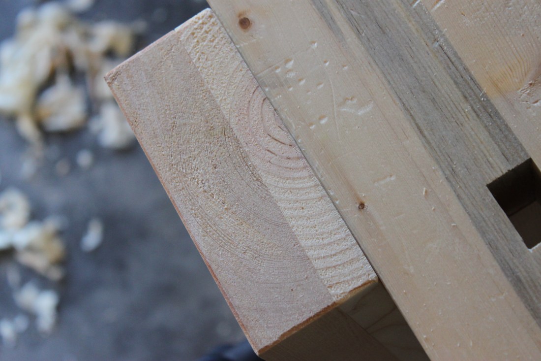
Next was working on the parallel guide. Since I had already cut the through mortise when I assembled the legs it was just a matter of transferring location on to the vise. I couldn’t take the measurements and mark it out on the leg vise because I had already cut the tapers, so I clamped the leg vise to the leg of the bench and did my best to trace out the mortise for the parallel guide. After I couldn’t get a good trace with a pencil I took a chisel and lined it up with the walls of the mortise as best as possible and marked it out. 
After the mortise was cut I made the parallel guide to fit snug in the leg vise but a hair smaller than the mortise of the bench leg so things would slide smoothly. Once I was happy with the fit I bored out the 3/8″ holes which were offset by 1/2″.

If you think that the parallel guide is ugly, just wait… Now that I had all the componets complete it was time for a dry run without the screws on the vise. Everything seemed to move smoothly so I figured I was ready to tighten things down. For some reason I decided to do this with the vise half way pulled out. When I went to check the fit I actually got it stuck. I could close it all the way but getting it to back out I had to reach under and lift the parallel guide for it to come loose. At first this worried me and I couldn’t think of what I was doing wrong. I’m gonna blame it on the fact that it was probably around 10pm and maybe after a beer or two. After some tweaking around a bit I figured it out. I closed the vise, clamped it down and then tightened the hardware. This gave me a smooth operation all the way in and all the way out. 
I don’t have any fancy draw bores or wooden pegs so I just use what I have and in this case it’s a allen wrench. 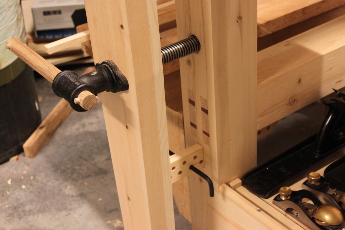
Now I didn’t really document the sliding dead man but I did want to show how ugly it was. Auger bits and pine do not seem to like each other. No matter what I did, drilling fast or slow, little pressure or a lot of pressure, things were just UGLY. I honestly think it’s the “craft” wood from the big box stores because I didn’t get these results with I drilled out the mortises on the 2 by material. 
Blow out on the back was horrible, even with a sacrificial board and predrilling the back. It is only the back so I’m not worried but I hate how compressed all the fibers are in each hole. These are 1″ holes offset by an inch so I just used the same oak dowel that I made the handles with. Overall it slides real smooth considering the track and groove are a less than perfect fit. I’m real happy with the functionality of both devices but if I could just finish up the top soon I’d be really happy. My goal is by the year’s end.
